Modification of X10 220V Heavy Duty Appliance module for use with 3 Phase systems.


Background: X10 home automation modules allow for control of a variety of devices.  X10 sells both 15 and 20 A "Heavy Duty" appliance modules for controlling 220V appliances.  My automation goal was simple:  I wished to turn on the air conditioner at my vacation home before leaving, thus having it cool on my arrival.  I have only DSL with a wireless acess point there, so elaborate computer based systems are out.  I set up an X10 system with a Dataprobe Web-X10 controller to allow for remote access. The Web-x10 provides a simple web interface to control a CM-11a on site.  A sonicwall TZ170 maintains the DSL connection and a VPN connection to my other residence for secure remote access, as well as providing wireless access when I am there.  When I plugged in the appliance module it didn't work.   All the other 120 V modules worked, and I tested the 220 volt module at my other house and it worked there, so I knew it was not a defective module.  The electrical panel appeared to be split phase (not a three phase panel) and the utility is billing me for "single phase" service.  As it turned out, the building had three phase service, and it is well described that the 220 v appliance modules won't work with a three phase system.

Further information about 3 phase power and X10 can be found on Ido Bar-Tana's excellent page.

In order to understand why the module won't work on a three phase circuit, it is necessary to review both how the X10 protocol works and how a.c. power is delivered.

First X10:  The X10 protocol uses a 120kHz carrier over the power lines and uses pulse code modulation timed with the zero crossing of the a.c. power line.  One bit is transmitted per power line cycle.  The X10 modules listen for the 120kHz signal when the zero crossing  is detected  (the zero crossing is the brief instant where the sine wave of the a.c. power crosses ground and there is momentarily zero volts across the line).   Modules can therefore  use the a.c. line to syncronize their reception of the power line carrier.   The approach works pretty well since an entire home is supplied by the same line.  American homes are typically supplied with "split-phase" single phase power.  Basically the stepdown transformer is center tapped, with the center tap grounded to form the neutral.  Thus, there is 120 volts between neutral and either pole, or 240 volts between the two "hot" leads.  The electrical panel usually alternates between the poles to balance the load.  240 V appliances use both poles.  The X10 signal will not pass through the inductance of the utility transformer.  The problem is well described elsewhere and can be resolved by putting a capacitor between the phases to couple the 120kHz signal.  The important point is that both "hot" leads cross zero together.  Thus where the two phases cross corresponds with zero on both phases,  and can be used by the appliance module as a zero crossing reference (Figure 1 and 2).

Three phase power:  Electricity is generated in three phases (Figure 3).  This provides both greater efficiency, and, if all three phases are used, the current never drops to zero.  To provide split phase single phase power, the utility puts a center tapped transformer on one of the three phases and sells you the output.  In order to keep the load balanced, a different phase is used to supply the neighboring transformer.  Typically one transformer supplies several homes.  Three phase power is also used.  A three phasee transformer can be wired as a "Wye"  with the center grounded, and supplies 120V on each phase.  This can be supplied to a three phase panel, and used to supply 120V single phase branch circuits.  A triple pole breaker can be used for 3-phase appliances at 208V.  A double pole breaker can be used to supply a single phase 208V appliance by connecting it across two of the three phases.  The difference between the phases is less since they are 120 degrees out of phase.   This is what the utility did in my building (Figure 4).  There are 12 apartments, each of which gets 2 phases.  Each apartment gets two of the three, and it is wired so each of the three goes to 8 apartments.   Since X10 times the pusle code modulation to the zero crossing and since the module references the zero crossing to zero potential coming in through the line, the zero crossing observed by the module will come at the wrong time.  X10 partially addressed 3 phase power by requiring that the 120kHz pulses be sent not only at the zero crossing, but also be repeated at 2.778 and 5.556 miliiseconds (60 and 120 degrees) after the zero crossing to cover the zero crossing of the second and third phase. (Figure 5)
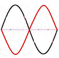
Figure 1:  One cycle of split phase AC power.  One phase is shown in red and the other in black.  Note that the phases are 180 degrees apart.

Figure 2:  Split phase AC power.  Note that both phases cross zero together, as marked by the vertical red bars.  The phases cross each other at zero.  In other words, when there is no potential difference between the phases, there is also zero potential to ground as well.  at 90 and 270 degrees, the difference between phases is at its maximum potential (long green line)  The short green marks indicate the timing of X10 pulse transmission.  The two pulses after the zero crossing are designed to coincide with the zero crossing of the second and third phase.

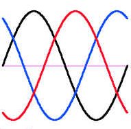
Figure 3:  3 phase AC power.  Note the three phases are 120 degrees apart, and each phase crosses zero independently.  Because of this, three phase power is more efficient since there is always voltage present.  With single phase power, current stops flowing briefly 120 times per second during the zero crossing.

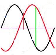
Figure 4:  Three phase power as applied to the appliance module.  For 208V three phase, only two phases are used.  The peak potential between the phases (green line) is less than for single phase circuit since one phase (red in this illustration has passed its peak while the other is approaching it.  Note that the zero crossings relative to baseline (pink line) do not correspond to where the phases cross each other (thin vertical red lines).  The appiance module does not have a ground reference (the pink line in this case), so the zero crossing detector detects zero crossing when the phases cross.

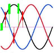
Figure 5:  Three phase power showing timing of X10 signals.  Note that the X10 signals are sent and correspond to the zero crossing of each of the three phases.  Note that at the crossing of any two phases (red bars, and what is detected as zero by the 220V appliance module, no X10 signal is present).   The designers thought about 3 phase power, but didn't consider 208 V three phase, or they would have transmitted 6 pulses per cycle, one every 30 degrees (1.389 ms).  With 50 Hz power, the problem is worse, since if a 60 Hz transmitter is used, the second and third phase will be mistimed.  It probably would have been better if they just made the pulse last for the entire half cycle.  But they didn't.


So what are the options to deal with this problem:
The first three options require too much work, and would hamper use with prewritten applications.  Building in a delay would require adding circuitry for which there isn't much room in the module.  So, the options are limited to the last two.  I tested the module by making an adapter to run it on 120 VAC.  It works.  One could isolate the electrical supply to the module (except the power detect line, which is isolated through a 330k ohm resistor) and power the circuit from a 120 VAC outlet. 

But, a closer examination of the circuit reveals another option:


Note that D3 and D5 clamp the voltage between 0 and +15 V.  Phase one is applied to Vcc and is regulated to create logic ground.  The other phase is applied through R2.  When the phases cross, a transition occurs at pin 1 of R3 which is fed to the zero crossing input of the 78570.  Suppose we move pin 2 of R2 to neutral.  Then when the first phase crosses neutral, the zero crossing will be detected.  This is exactly what we want!  But we don't have a neutral wire in the module. 

Ground and neutral are tied together in the main electrical panel, but nowhere else (per NEC).  Therefore, ground and neutral are electrically equivalent.  The reason it is against electric codes to use the ground wire as a current carrying conductor is safety.  If the integrity of the current carrying ground were to be interrupted, say by a loose ground pin, loose raceway, or loose ground wire, the outside of the appliance would become electrified through the relatively low impedence of the appliance.  If a human were to touch it, most of the voltage would be dropped across the relatively high impedence of the human body, possibly causing electrocution.  Fortunately, with 330k ohms, there is a potential for only 0.4 mA of ground leakage.   For safety, a separate ground of the appliance using a cold water pipe should be considered, especially if the appliance is a hot tub.  A ground fault circuit breaker should also be used.  Most GFCI's trip at 3-5 mA of ground leakage.  If the modification is not done correctly, there is an even higher potential for electrocution.  If a neutral wire is available in the box, or can be pulled (in the case of conduit wiring), it should be used.

You can tell if you have a three phase system by:

Modification

WARNING: This information is provided for educational purposes only.  Any modifications to X10 modules are potentially EXTREMELY dangerous.  You will void your warranty and invalidate the CSA/UL listings by making modifications.  Additionally, there are hazardous voltages present if plugged in with the case open that can cause DEATH BY ELECTROCUTION OR SEVERE BURNS.   Further, using the ground as a zero reference exposes you to ground fault condition, if there is an open ground, the outside of the controlled appliance could become electrified AND CAUSE ELECTROCUTION.  THE APPLIANCE SHOULD BE INDEPENDENTLY GROUNDED TO ANOTHER SOURCE SUCH AS A METALLIC COLD WATER PIPE.   Miswiring may also result in FIRE or SMALL EXPLOSION.  PROCEED AT YOUR OWN RISK.  I take no responsibility for any untoward consequences of using this information.  Using the ground as zero reference SHOULD result in no more than 0.4 mA of ground leakage IF WIRED PROPERLY.  It is up to the user to completely understand what they are doing and the ramafications of this modification, and to determine if the modification is suitable to their intended application.

Figure 6:  The outer housing has been disassembled by removing the four screws in the corner.  The module acutally contains a wall outlet module.  I would assume this modification could also be used on the receptacle version of this unit. disassembled housing
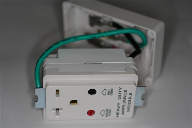
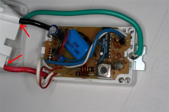
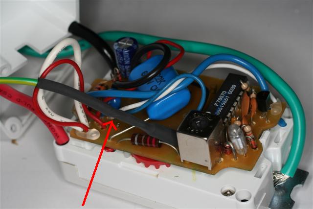
Figure 7:  The receptacle module itself is opened by removing the two screws on the back and carefully sliding the cover down the power leads (red arrows).  It is not necessary to remove the circuit board for this modification.  Note the smaller black (upper left) white (lower left) and blue (diagonal upper right to lower left) wires.  These provide power (each of the two input phases) through the black and white, and power on detection through the blue.  Functionally, the white wire is the same as the neutral in 120 VAC applications.  (It is NOT neutral here)

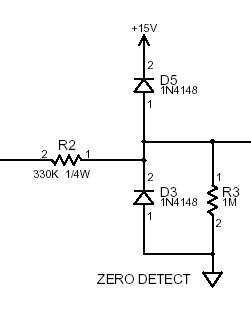
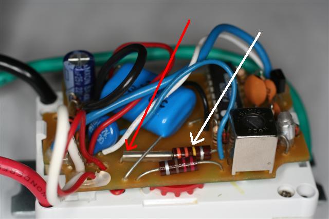
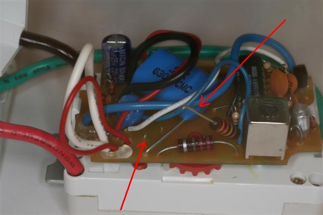
Figure 8:  Identify the 330K (orange-orange-yellow) 1/2 watt resistor.  This resistor couples the zero crossing signal from the Line 2 ("neutral" in the device schematics, actually the opposite phase of the input) to the IC.

Figure 9:  Cut the lead of the 330K resistor as shown and remove the sleeving.  Cut the lead as close the the circuit board as possible.

Figure 10:  Solder a length of wire to the cut end of the resistor  lead.  Place heat shrink tube over the resistor and connection as shown.  To bring the lead out of the housing, you can either drill a hole in the back, or bring it out through one of the unused corner holes.  If you use the corner holes, you'll have to make a notch at the inside to allow the case to close all the way (area shown with arrows in Figure 2, but on the opposite side).

Once outside, the wire may be connected to the ground prong.  You can disconnect the connector and solder it on.  If you are mounting the module in a  junction box as a receptacle, the wire should be connected to "neutral." (the grounded conductor), and white wire should be used.

That's it.  Carefully reassemble the module being careful not to pinch any wires.   An ohmmeter check is recommended.  Measure the resistance between each blade of the plug and the round prong.  If either is less than 330,000 ohms, recheck your wiring before using. 

Plug the module into the 220V outlet without an appliance plugged in.  Send "ON" and "OFF" commands and listen for the click of the module.  If you don't hear it, go back and check your work.  It could also indicate a defective ground.

Not pictured: there is room in the housing to put a 0.1 MFD 600 V capacitor and 18 mH choke in series across the line to allow the module to also serve as a phase coupler.